Gear design and analysis

An expert software dedicated to plastic gears optimization

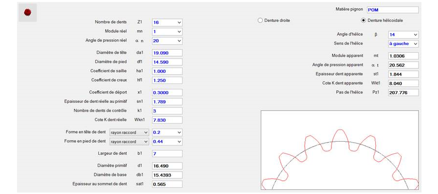
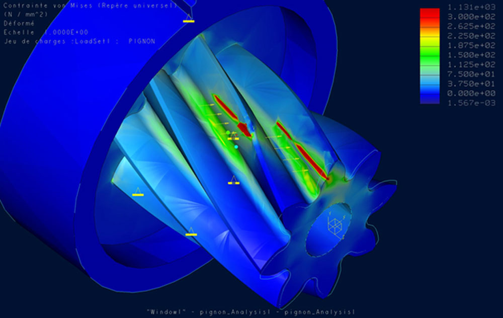
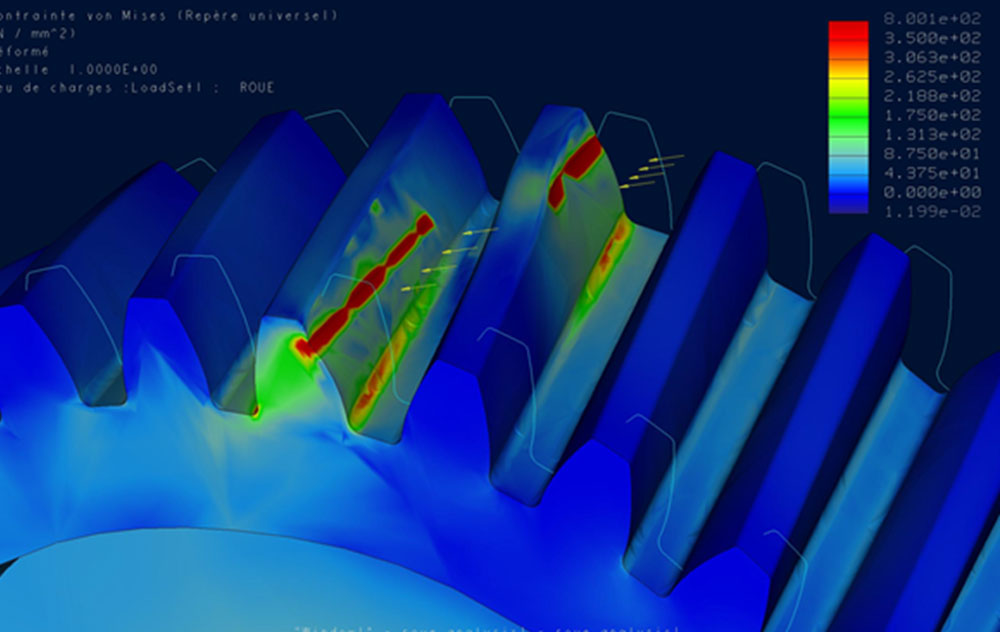
Apart the usual software that are currently used in mechanics engineering for plastic parts such as CADs systems, FEA and other rheological analysis, our study department felt the need to develop from the 90's, its own expert software which purpose is to define and optimize gears and gear-trains according to customers requirements (torque to transmit, overall dimensions, environmental conditions, noise reduction...). Our software takes into account physical properties of the various plastic materials that can be chosen.

This engineering tool is of valuable support to carry-out our studies and to share with our customers the best gear design :
- The reason why it is so good
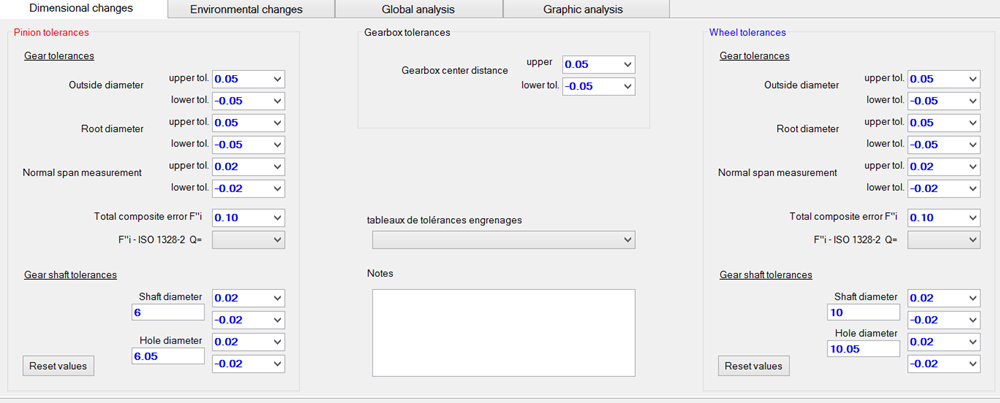
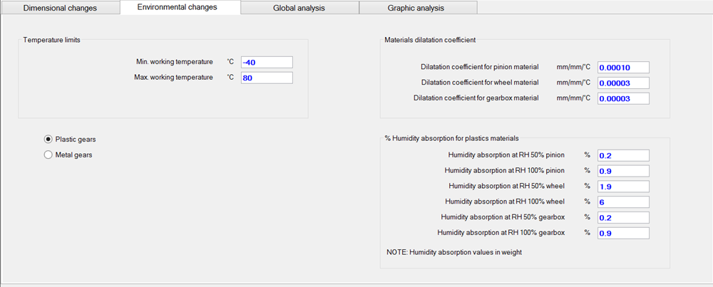
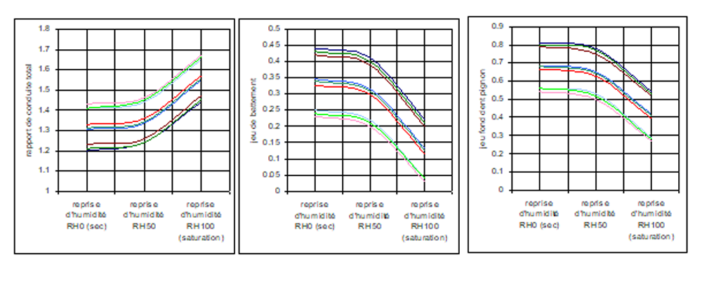
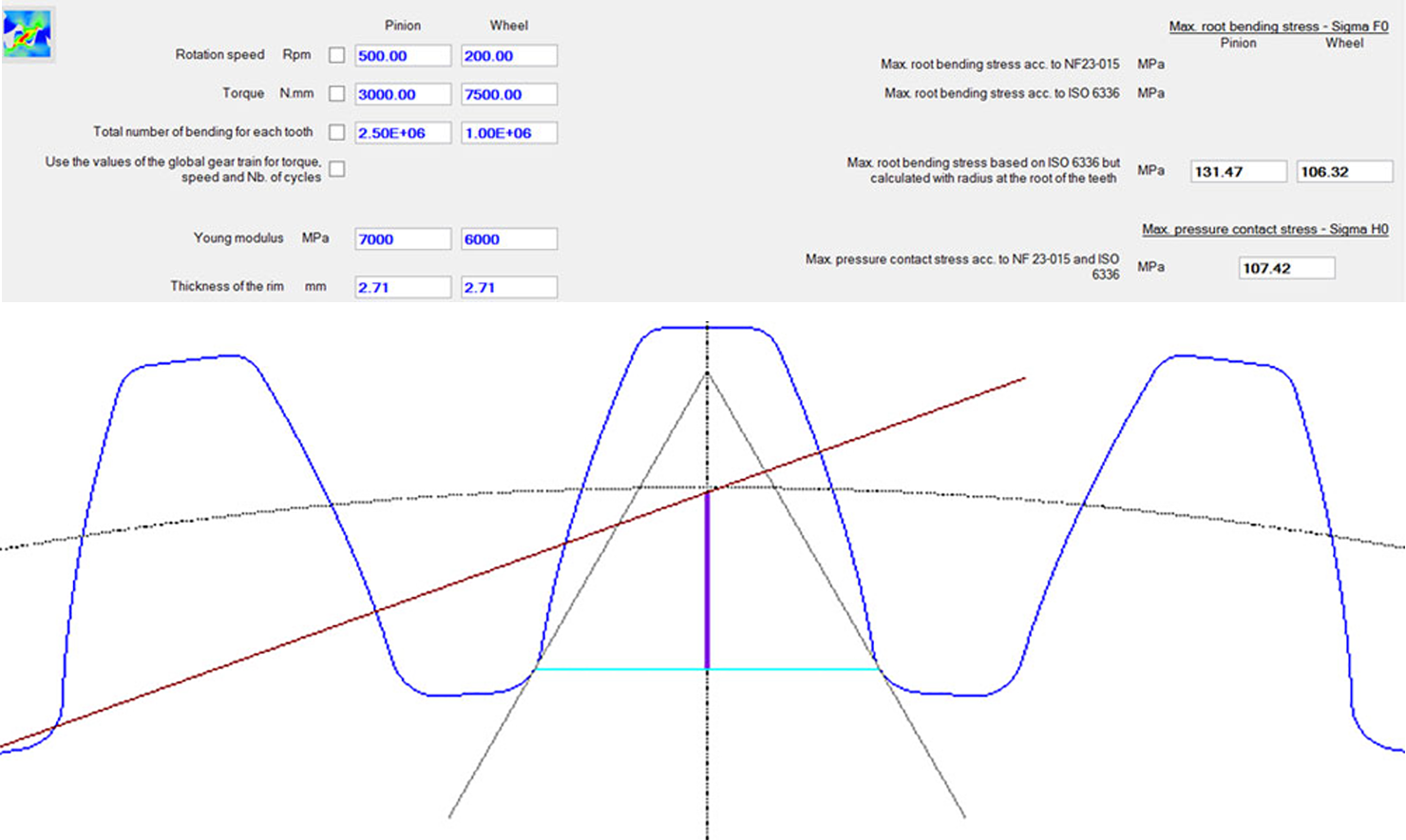
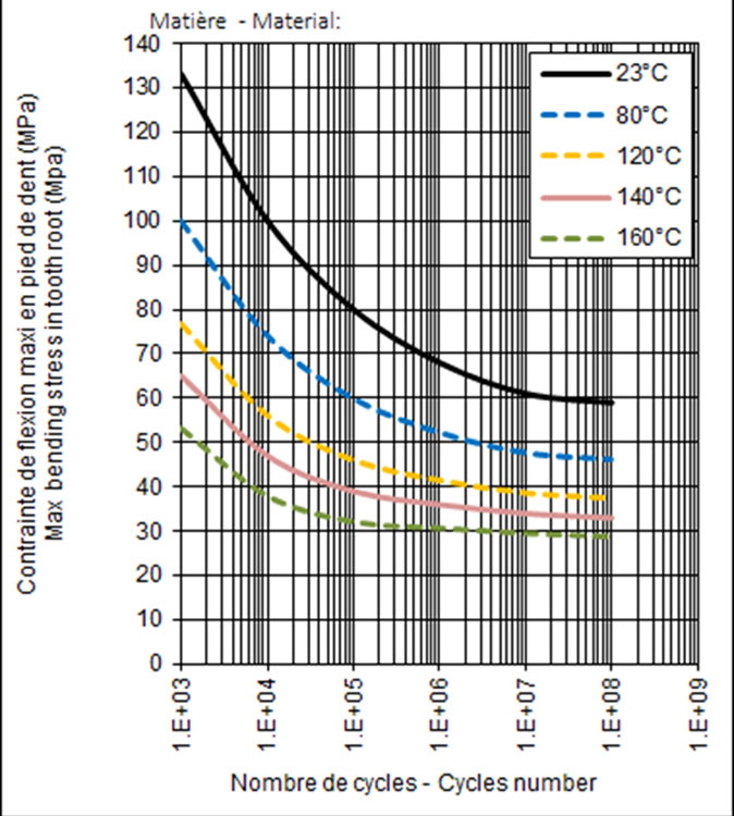
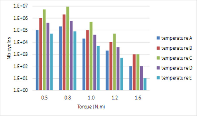
- How it will operate at limits of the various parameters such as temperature, moisture, fatigue, backlash and tolerance limits...


We use our software to define and optimize the gear data according to the physical properties of plastic materials.

For example, we define for each gear what follows : pressure angle, helix angle, shift coefficients, tip and root diameters, center distance, tip and root filets,


The structure of gears may have significant impact on their accuracy. For example, a hole across the rim of the gear will result in a material welding line which will be of less dimensional stability than in the rest of the gear, where there will be no welding line. Reinforcing ribs may have similar impacts. In addition, dimensions aren't the sole criteria impacted by the design of the gear structure : the mechanical strength, noise and cost can also be badly impacted. We know how to optimize the gear structure in order to limit at best its poor influence on the above mentioned criteria in the first rank of which is the gear accuracy.
 

EXAMPLE OF STRUCTURE ANALYSIS OF A WHEEL MADE BY FINITE ELEMENTS


Our experience and continuous improvement in the field of plastic gears have enabling us to enhance our database so that we can estimate at best, early in our developments, the realistic tolerances which can apply to the whole gear actuator (gears, bearings, center distances, …). These achievable tolerances depends on the material in which gears, gear-housings and bearings will be made, but also on the type of gear, the structure of its rim, its modulus and the chosen injection system. One of the secret for functional robustness of our gear-trains consists in taking into account realistic tolerances when designing gears themselves. We can indeed optimize some criteria such as shift coefficient, pressure angle, helix angle, to compensate a low contact ratio or a large tolerance width in center distances for example. 


To get a robust actuator design, we also analyze how the gears mesh together in the limit conditions of dimensional tolerances, temperature range and humidity. With plastic materials, the variations of dimensions due to temperature & humidity may be significant. This is the reason why it is of great importance to check how gear-pairs operate at specified dimensional & environmental limits. To do so, we have developed a dedicated calculation model which we call : Gears at Boundaries Analysis © (GBA©) 


GEAR MESHING ANALYSIS


The criteria that are analysed carefully at boundaries conditions for each gear-pairs are, among others :
- Total contact ratio
- Backlash between the teeth flanks
- Clearance between tip and root diameters
- Specific sliding coefficient
- Theoretical working interference


On designing gears there are, among others, two Important criteria on which we have to keep an eye :

- The stress level at the root of teeth in order to avoid tooth break concern

- The Hertzian pressure on the flanks of teeth which may results in surface mating or wear concern should it be too important.

We assess these two criteria - tooth root stress and contact pressure - either by analytical method or by Finite Elements Analysis (FEA).
 

EXAMPLE OF TOOTH ROOT STRESS CALCULATE BY ANALYTICAL METHOD


EXAMPLE OF TOOTH ROOT STRESS CALCULATE BY FINITE ELEMENTS ANALYSIS


The mechanical strength of plastics changes significantly according to the temperature range. In addition plastic materials are also very sensitive to the number of bending cycles (fatigue phenomenon).

Therefore, to achieve a robust definition, we have to take into account these peculiar properties of plastics in gear design calculations. 

ITWSmpi does have the necessary plastics database to do so and is very experienced in this kind of calculation. 
 

EXAMPLE OF FATIGUE LIMITS AT DIFFERENT LEVELS OF TEMPERATURES AND NUMBER OF CYCLES :


For often the torque isn’t constant during the life of the gearbox. If our customer is in position to provide us with the spectrum of loads versus the number of cycles & the temperature, then we can also calculate a fatigue accumulation stress.

We integrate these data into our specific calculation model of Cumulative Damaged Analysis© so as to obtain a more accurate assessment of the safety coefficient.
 

INPUT DATA: SPECTRUM LOAD VS NB. OF CYCLES & TEMPERATURE


OUTPUT DATA :
- FATIGUE ACCUMULATION STRESS
- SAFETY COEFFICIENT